使用宽带电压和电流反馈运算放大器时的应用基础
The following example circuits should use a VFB device for implementation.
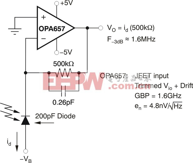
A. Transimpedance amplifiers. These circuits take a current source input, typically from a capacitive source, and turn it into a voltage at the output. The feedback resistor is the gain element and normally needs a compensation capacitor in parallel for correct operation.Figure 6shows an example using the OPA657, a very wideband JFET input device uniquely suited to the transimpedance application. This device is a non-unity gain stable VFB with relatively low input noise voltage and very high gain bandwidth product. For a given diode source capacitance, the amplifier gain bandwidth product (GBP) determines the achievable bandwidth and/or transimpedance gain (Reference 3).
(Click to Enlarge Image)
Figure 6. Example transimpedance design using the OPA657.
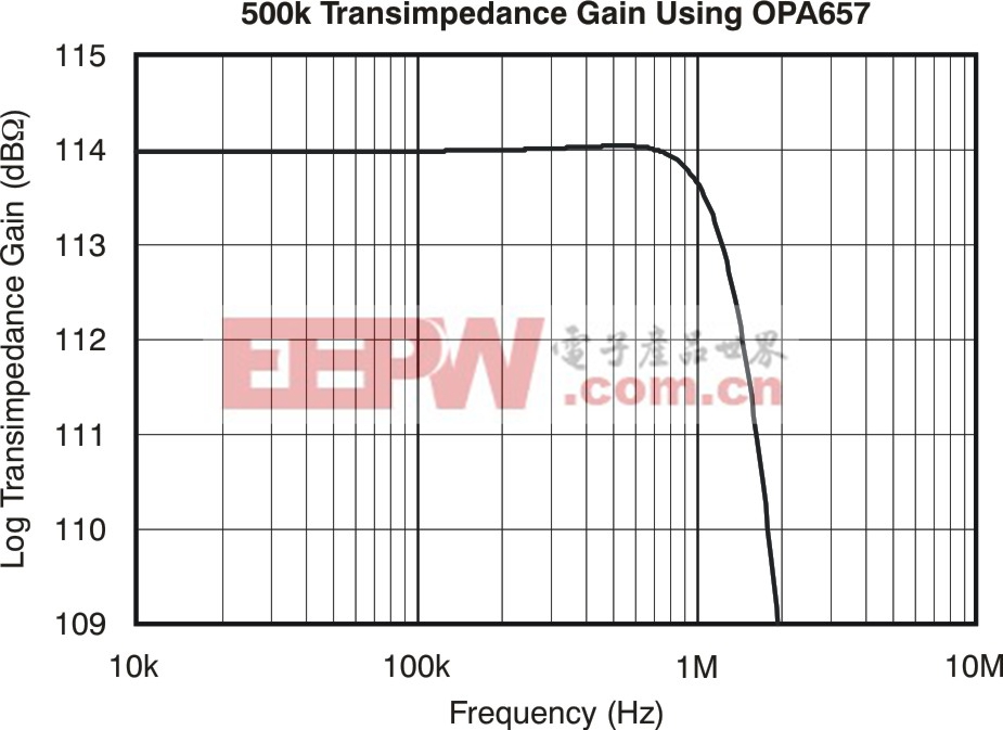
In this example, the 500 kΩ along with the 200 pF diode capacitance gives a noise gain zero at approximately 1.6 kHz. With the feedback capacitor set to achieve a maximally flat Butterworth response, the resulting F-3dBwill be at the geometric mean of this zero and the 1.6 GHz gain bandwidth product of the OPA657. (Reference 3 gives a detailed analysis for compensation and noise in a transimpedance design.)Figure 7shows the 1.6 MHz transimpedance bandwidth in a simulated frequency response of Figure 6.
(Click to Enlarge Image)
Figure 7. Simulated transimpedance frequency response of Figure 6.
B. Integrator based circuits. These applications are looking for a capacitive feedback to implement an integrator function. A good example would be the Multiple feedback (MFB) active filter.Figure 8shows an example using the OPA820, a low-noise, wideband voltage feedback op amp uniquely suited to this application.
Embedded within this filter circuit is an integrator configuration that arises from the 200 Ω and the 12.5 pF feedback capacitor.
At very high frequencies, that capacitor shorts out, giving a local unity-gain feedback for the amplifier. This result suggests that a unity gain stable VFB should be used in this type of circuit to avoid high frequency oscillations. This particular example is targeting a 10 MHz low-pass Butterworth response with an in-band gain of -4 V/V. (Reference 4describes how to ch

加入微信
获取电子行业最新资讯
搜索微信公众号:EEPW
或用微信扫描左侧二维码