逻辑探针电路图,LogicProbe
作者:dolphin
时间:2012-11-09
逻辑探针电路图,Logic Probe
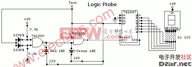
This circuit is a Logic Probe. It indicates the logic state of the node of any TTL logic circuit. To do that, we have to supply the probe with the same power of the circuit that we want to analyse: same Vcc and same GND. To check the logic level, we must connect the "Test" wire of the probe to the desired node of the circuit that we want to check.
If the level is Low, the probe will display a "zero" (0) and border=0>
关键词: 逻辑探针电路图 LogicProbe 电路图

加入微信
获取电子行业最新资讯
搜索微信公众号:EEPW
或用微信扫描左侧二维码