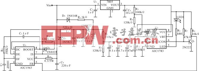
步进电机控制器电路 Stepper Motor Contro
步进电机控制器电路 Stepper Motor Controller
I found this circuit in my files. I don't know where it came from, but it looks like I photocopied it from somewhere years ago. I have been told that it came from "The Robot Builder's Bonanza", by Gordan McComb. Anyway, I thought that it should be fairly useful, so I decided to post it here. The circuit is very simple and inexpensive. This is good thing because most commercial stepper motor controller ICs are quite expensive. This circuit is built from standard components and can easily be adapted to be controlled by a computer. If you use cheap surplus transistors and stepper motor, the price of the circuit can be kept to under 10.
Schematic
Parts
Part | Total Qty. | Description | Substitutions |
R1, R2 ,R3, R4 | 4 | 1K 1/4W Resistor | |
D1, D2, D3, D4 | 4 | 1N4002 Silicon Diode | |
Q1, Q2, Q3, Q4 | 4 | TIP31 NPN Transistor (See Notes) | TIP41, 2N3055 |
U1 | 1 | 4070 CMOS XOR Integrated Circuit | |
U2 | 1 | 4027 CMOS Flip-Flop | |
S1 | 1 | SPDT Switch | |
MISC | 1 | Case, Board, Wire, Stepper Motor |
Notes
1. You should be able to substitute any standard (2N3055, etc.) power transistor for Q1-Q4.
2. Every time the STEP line is pulsed, the motor moves one step.
3. S1 changes the motors direction.

加入微信
获取电子行业最新资讯
搜索微信公众号:EEPW
或用微信扫描左侧二维码