超声波测距如何在智能小车中进行应用?
3 Design and mechanical structure of the push rod
This section will mainly describe the self-designed bread-pushing rod and its operating principle. The process about how the robot pushes the rod in order to throw the bread into the lake.
The rod will stop as soon as the distance between the rod and bread is less than 20 centimeters. The battery will supply the energy to the micro-controller. In this project, mbed is used to perform this function. The energy will make the gear motor rotate, when the gear is activated, it will push the rod ahead and the rod will push the bread forward. And finally after a certain time (we estimated the time that the bread can be pushed away) the motor will rotate in the opposite direction and take back the rod.
Then some details in the process will be discussed. First is about the energy supply. At the beginning, the battery supply the energy to the mbed, but it is not strong enough to drive the motor. So between the mbed and motor we added an inverter to connect them. If a low voltage is given to the input of the inverter, it will output a higher voltage which is strong enough to make the gear rotate. Then it’s about how to push the rod by rotating the gear. The motor will make the gear rotate in clockwise after it accepts the command from the mbed. Then it will push rod ahead until for a certain time and after that the gear will rotate in the opposite direction to take back the rod. Besides, we place a rack which is in series with the rod and its insections are completely matched to the gear.
In the mechanical part, two plastic splines with teeth and a small DC-motor with a 5V supply voltage are the main components used.
There are some basic requirements. The first is the whole bread-pushing part must be easy to control, which means it should be able to be controlled based on simple code instructions, and the structure shall not get stuck itself during the motion process. The second is the part must be firm and reliable, which will bring more flexibility for other parts to error while it doesn’t do so itself. The third is the part shall be modifiable to a certain extent, so that the structure could be fixed or adjusted due to real situations and demands.
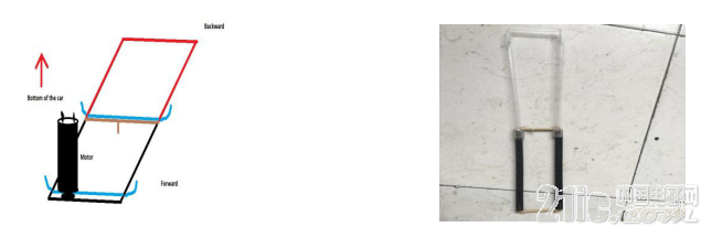
Figure 3.1. Figure 3.2.
A graphic of the bread pushing rod Picture of the bread pushing rod
At first, including the final version, there are three main possible solutions, namely, splines and a motor, a mechanical arm, a simple-structured single-use slingshot-like module. However, the mechanical arm is a bit too big for the scale of the body of the car, and hard to be programmed at the same time. Meanwhile, the slingshot structure is resistless to physical impact and vibrations, which will possibly result in high rate of spurious triggering during the advance. Thus, at last, the splines and a motor is chosen as the solution, due to its simplicity of programming with only one motor.
For the assembling of the structure, the supportive parts are self-made, due to the incompatibility of the default module. In practice, the self-made structure is proved to be efficient and good enough to stretch out and draw back.

加入微信
获取电子行业最新资讯
搜索微信公众号:EEPW
或用微信扫描左侧二维码